Technical data:
Fq 1296.800 MHz
Est freq drift < 26 Hz per year
Pout 42.4 dBm (17.4 W) into cable (measured 20000913) after maintenance (20240911) Pout = 42.7 dBm
Keying A1A ( 3x "SK6MHI" + 1x "SK6MHI JO57TQ"... carrier on for approx 45 s)
Key up/down > 80 dB
Antenna Alford slot, approx 7 dBi +/- 2 dB (360 deg)
Cable loss approx 2dB
Estimated EiRP 47 dBm +/-2 dB (50 W +/-2 dB)
FREQUENCY ACCURACY
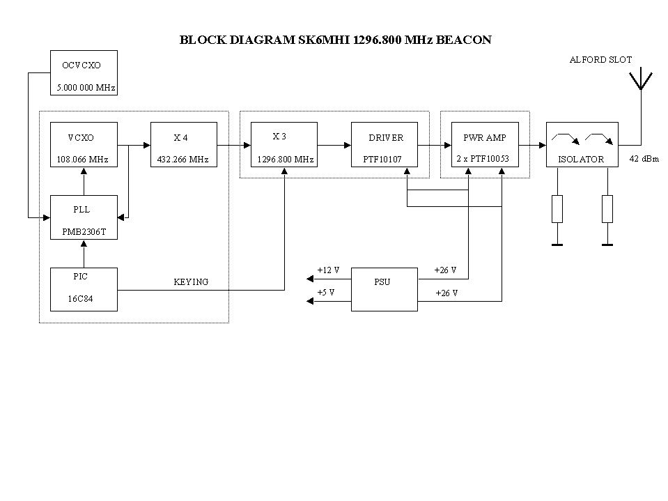
Beacon frequency is locked to a 5 MHz OCVCXO. Specification for the oven is +/- 2E-8 overall frequency stability over 1 year. This gives that the beacon frequency should not drift more than 26 Hz per year. Frequency has been adjusted to nominal 1296800000 Hz by a rubidium locked frequency counter in July 1999.
Beacon frequency was checked 20240911, 1296.799 970 MHz, measured with a frequency counter locked to a Leo Bodnar reference. Adjusted back to 1296.800 000 MHz 20240911
Technical description
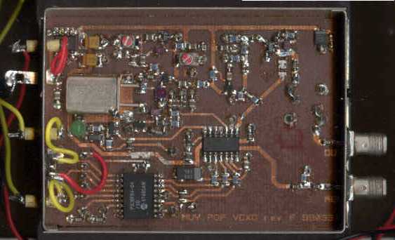
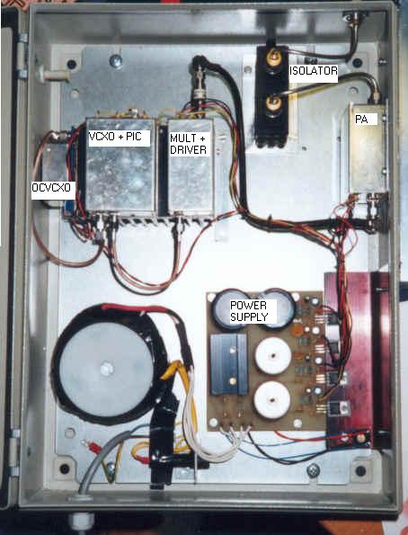
VCXO
The VCXO is an emitter harmonic oscillator with a capacitance diode from the xtal to ground. A PMB2306T from Infineon (Siemens)is used in the PLL-circuit. The PLL dividers are loaded from a PIC (16C84) at power on which then (the PIC) goes into beacon mode and generates the keying of the beacon. The buffer amp in the VCXO box is driven into compression and generates harmonics, the fourth harmonic is filtered by a helixfilter (432.266 MHz).
x3 MULTIPLIER AND DRIVER AMPLIFIER
The 430 MHz signal is fed into the next amplifier MSA-2111 which is also driven into compression and the third harmonic is filtered out by the 1296 MHz helixfilter. The 1296 MHz signal is amplified and filtered, output power from this box is approx 30 dBm. Keying is accomplished by keying the voltage feeding the MMIC amplifiers. The last stage in this box is a LDMOS amplifier using a ERICSSON PTF10107 GOLDMOS (5 W device) that gives 15 dB of gain.
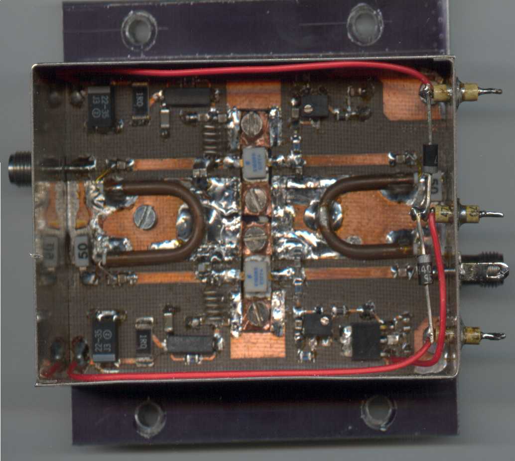
POWER AMPLIFIER
The PA consists of two ERICSSON GOLDMOS PTF10053 (12 W device) and wireline hybrids. Matching networks are simple 50 ohms microstrip lines with capacitors to ground. The two LDMOS stages are feed with 27 V from independent voltage regulators. In case of failure in one of the FET:s the other one can still operate and the beacon will lose 3 to 6 dB of output power. The driver amplifier gets its voltage (26 V) from those two separate voltage regulators via diodes.
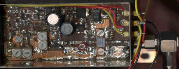
PSU
The power supply is a simpel ordinary design. It uses PTC resistors on the secondary side as fuses. There are four separate voltage regulators 8V, 12V and two for 27 V. The 27V regulators supply each side of the PA.
ANTENNA
The beacon antenna is an ALFORD SLOT which approximately have 7 dBi of gain.
Inside SK6MHI
Maintenance report, or what did go wrong, after 24 years. (in swedish)
Changed 2024-09-22 by SM6PGP