Designed by SM6PGP, Hannes
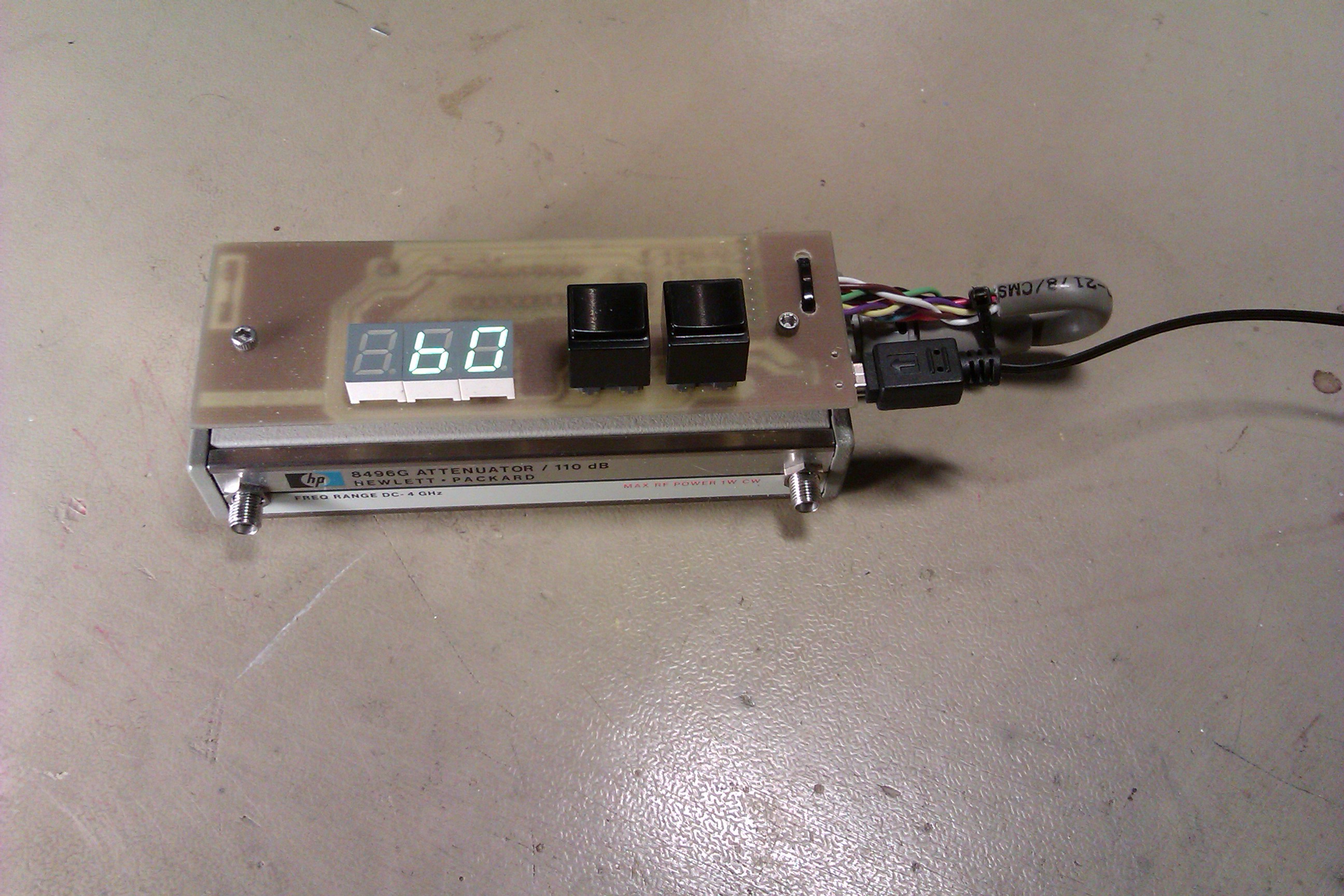
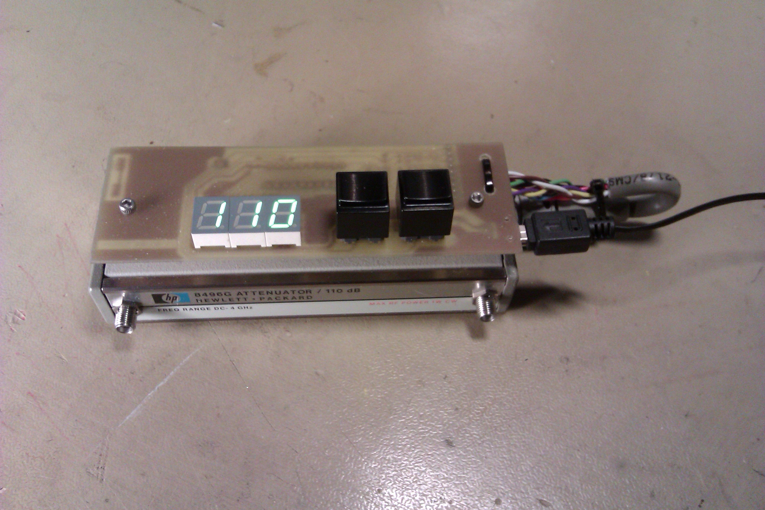
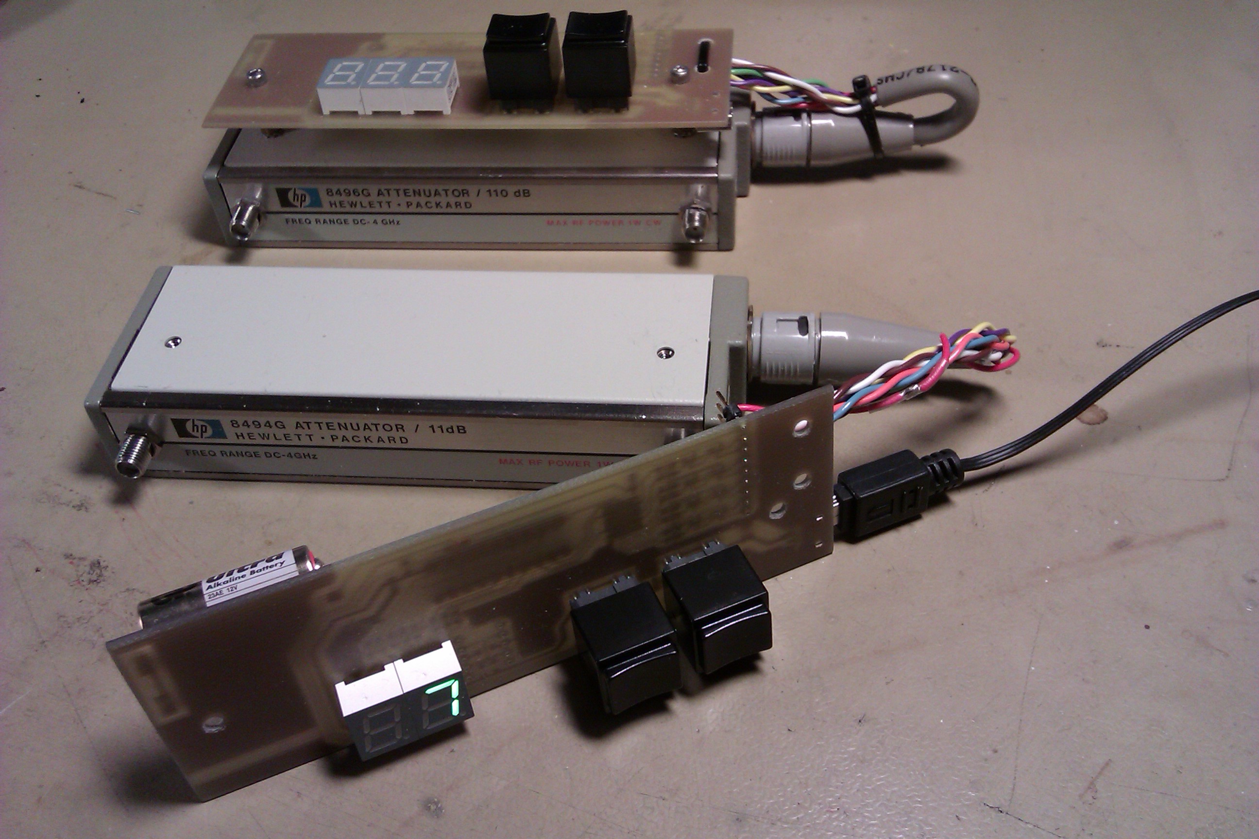
A couple of years ago (maybe already more than 10 years) I bought some very nice HP 8494G and HP8496G programmable step attenuators (electrically cotrolled - no manual ) at a fleamarket. The attenuators have been resting in the junkbox - REASON - no nice controller. Of course, four simple switches in a box would have done the job, but then no nice display showing the current attenuation. I started to think about a design with discrete logic - but soon found that it did not get as simple as I wanted, the number of components were just increasing - solution ---> a PIC processor. As the PICKIT2 was lying on the table with an unused 16F690, the choice was easy. The 16F690 is cheaper (half the price) than the well known 16F84 that I have used in other projects.
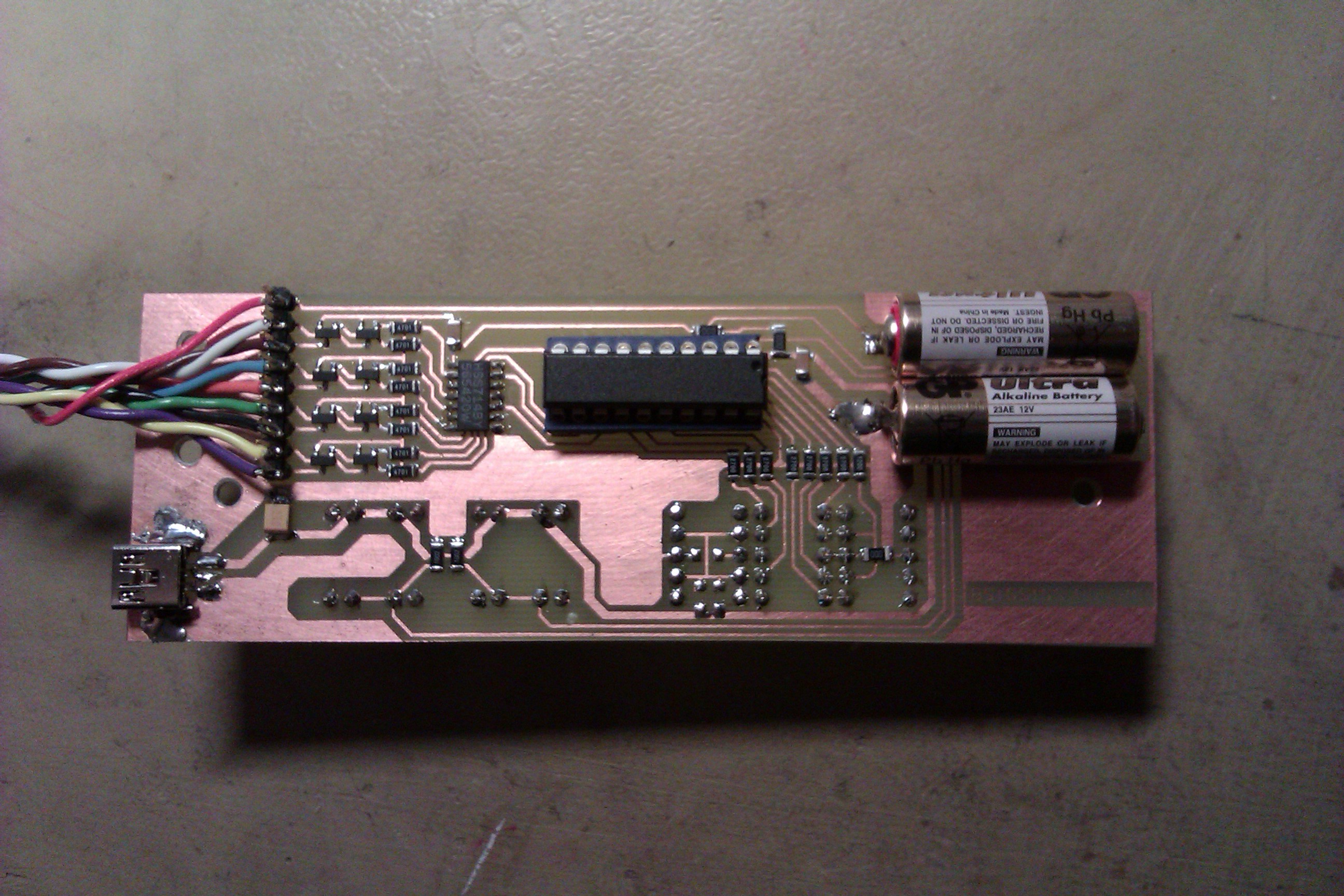
The controller is built on a single layer printed circuit board, the 7 segment LEDisplay and switches for up/down stepping is on the componentside of the board and the processor and other components are on the copper side. The PIC is mounted in an IC-holder for easy programming on the PICkit developing board. The other components are SMD type.
Two 7segment LEDs are used for the 0-11 dB attenuator and three 7 segment LEDs for the 0-110 dB attenuator.
The controller is powered by 5V from an USB connector - these small 5V power supplies are easily available almost every were. You can also use some old 5V mobile phone charger, they are often specified as 5V (or 4.9 V) and a couple of hundred mA. The current consumption is less than 200 mA. If neccesary to go portable it is enough to hook up a single LiPo cell, the circuit works down to 2.0V although the brightness of the display is reduced. The 24 V needed for switching the solenoids in the attenuator is simply supplied by two small LR23/MN21 12V batteries soldered to the back of the board. I thought about some DC/DC converter or some switched capacitor solution to get the 24V but as the current is only drawn for a very short moment < 20ms I think that these batteries will last for a couple of years. If not I will have to make a redesign. The cost for the batteries is less than 20 SEK/pcs (2 euro/pcs) and is a simple solution.
When turning the controller ON - it will go to maximum attenuation, 11 dB or 110 dB. The up and down buttons are used to step up and down - when reached max/min attenuation further stepping in that direction will not change the setting, it will not step from 110 dB to 0 dB as this could be " smoke generating" in the connected equipment or devices under test. The attenuator stays in the state it has when turning the 5 V supply off until it is turned on again when the attenuator goes to full attenuation.
Schematic in pdf :
Schematic in pdf (18k)
PCB layout in pdf:
Component placement /component list in pdf
Component placement in pdf (48k)
PIC Assembler code and compiled HEX-file
PIC asm and hex code for the 16F690, the code is as it is and i
have
not put much effort in the programming
as I am no programmer
and just do it because I have to.
Information on this page may only be used for
personal use, for any other use pse contact s m 6 p g p ( a t ) i l l i p e . s e
Changed 2014-07-26 by SM6PGP